Purpose
This feature allows you to apply loading for a mechanical device (FAU, A/C, etc.) without manually adding point loads. This loading can be applied to any truss bottom chord, regardless of type. At this time, this feature is for bottom chord applied mechanical loads only.
Steps
- Click the Component button on the main Design workspace.
The Component Loading dialog displays.
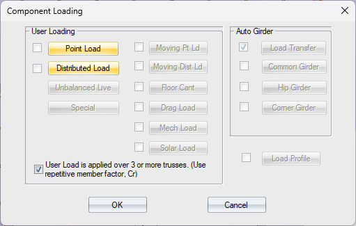
- Click Mech Load.
 Note: Selecting the Mech Load check box enables the "User load is applied over 3 or more trusses" option. Any and all Mechanical Loads that are entered in the Mechanical Load dialog (see below) are applied/not applied based on this check box. Unchecking the box disables all defined Mechanical Loads. Checking or re-checking the box enables all defined Mechanical Loads.
The Mechanical Load dialog displays.
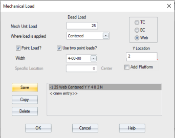
Complete the following settings and click Save:
- Mech Unit Load - enter the load amount
- Where load is applied - choose from Centered or Specified
- Apply the load to the TC, BC, or Web. If you choose Web, you must enter a Y Location.
- Point Load? - click if the load is a point load
- Use Two Point Loads? - click to use two point loads
- Width - this option is available when the Use Two Point Loads? option is turned on. Select a width from the drop down list.
- Specific Location - this option is available when the Specified load option is selected
- Add Platform - add a framed platform in trusses to lift mechanical units above insulation. Can only be applied between two webs with adequate room between them for a platform. Check Web to access this feature. This feature is only available in Design view.
See examples of how this setting is applied.
This example shows the application of two 25# mechanical unit point loads in the center of a 30' spread-web truss (not an attic room). The unit is 3-06-00 wide and will be spread over 3 trusses minimum.
1. Open the Mechanical Load dialog from the Component Loading dialog, and enter the 25# load.
2. Select Point Load and Use two point loads?
3. Set the Width to 3-06-00
4. Click Save and click OK.
5. On the Component Loading dialog, check User Load is applied over 3 or more trusses and click OK.
Resulting dead loads are applied at 13-09-00 and 17-03-00 on the bottom chord.
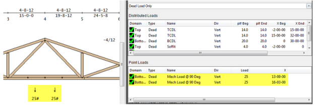
Note that the above was created by entering two user point loads. The Mechanical Load dialog is a shortcut to automatically obtaining the same entries.
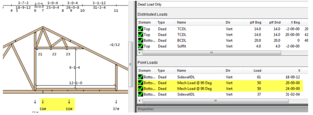
This example shows the application of two 50# mechanical unit point loads in an attic room, but the attic room is offset from the center of the truss and the mechanical loads are not centered in the attic room (they are on the left side). The truss is 40' long, the attic room is 12' wide and centered at 25'. The mechanical unit point loads are needed at 20' and 24'.
1. Open the Attic dialog and check Apply 'Mech Load to this space.
This initially places the two point loads based on default settings, but centered at the center of the room at 25 feet. Therefore, the point loads are at 23' and 27' (4 feet apart, per the default settings). The load is initially 25# at each location.
2. Edit the Mech Load dialog script, selecting the script that was created from the Attic dialog, changing the load to 50# and the Specified location to 22'.
Resulting loads are applied at 20' and 24' on the bottom chord in the attic room, as shown below:
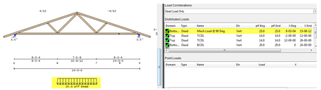
This example shows the application of a 25 PLF load in the center panel of a 24' fink truss. The load will be over two trusses only.
1. Open the Mechanical Load dialog and verify that Point Load is turned off and the Mech Unit Load is set to 25. Click Save and OK.
In this case, you would not select User Load is applied over 3 or more trusses on the Component Load dialog, since the load is over only two trusses.
The resulting load applied is as a 25 plf distributed dead load between the two bottom chord joints for the distance indicated in the Width option (show below as the full panel):
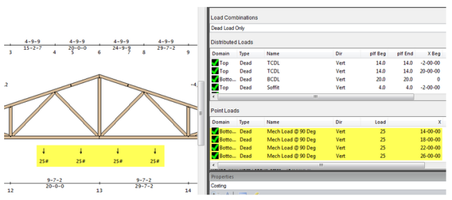
This example shows the application of two mechanical loads -- both are 25# point loads. 4' apart, One is on the left side of the 40' truss, centered at 16' and the other is on the right side of the truss, centered at 24'. Both loads will be over 3 trusses.
1. Open the Mech Load dialog and select Specified in the Where load is located setting
2. Verify the 25# load, Point Load and Use two point load options.
3. Set the Width to 4-0-0 (if not already) and the Specified location to 16 feet for the first unit location. Click Save.
4. Select the script from the above entry and click Copy.
Change the Specified location to 24' and click Save and OK.
5. Check User Load is applied over 3 or more trusses on the Component Loading and click OK to exit.
The resulting load is applied at 14', 18', 22' and 26' as shown below:
Note: 20 PSF storage loads and mechanical unit loads are separately considered when they apply in the same location. Turning off the Mech Load (or the LSC) causes that load to be removed from all load cases, including user load cases (copied or created from scratch).